Module’s Utility:
1. Compared with other CC2530+CC2591 modules, the signal is more than 5dB higher! Not afraid of goods than goods, I am afraid not to know the goods. As long as you know how to do it, as long as you try it, you can sigh that the original RF module is so deep, not everyone can do it!
2. The industry’s ultra-low price, mature and stable product quality, positioning in the Zigbee project promotion. The bulk price can be negotiated again! From then on, you only need to focus on application development, complex RF hardware we can help you!
3. Good cooperation with AVNET and TI Shenzhen Technical Support Center, the world’s largest chip distributors. The first-hand data of chips is obtained through FAE, matching high-frequency RF circuits, and the transmission power and receiving sensitivity are superior to other products. The CC2530+CC2591 module signal is 5dB higher than other products!
4. Adopt high-quality RF circuit PCB board, unique micro-belt line to replace the design of small parameter components, select high-precision and high-stability components to ensure higher performance, better stability and consistency than other products.
5. Compared with other RF front-ends, the CC2591 chip recommended by TI is used as the CC2530 transceiver front-end. The gain is higher, the programming is simpler, the technical support is more complete, and the functions of ZStack sleep low power consumption can be seamlessly realized.
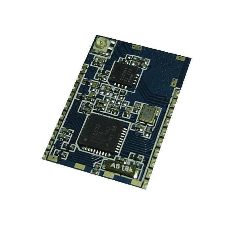
6. Ultra-small area (27mm*18mm), ultra-thin thickness (only 1.6mm when using on-board PCB antenna), can be easily embedded in terminals such as watches, MP3, active RF cards.
7. The stamp hole patch design using the RF module convention, supports SMT secondary patch, and provides the adapter board at ultra low price, which can be easily converted into DIP pin for development experiments. The ultra-low-cost package provides an excellent external antenna and antenna connection cable.
The module is an IPX antenna connector. Please purchase a built-in small-sized IPX copper tube antenna or an external IPX to SMA patch cord + SMA antenna kit. Otherwise, there will be no signal.
Transceiver’s Parameters:
What is the receiving sensitivity? Why is the receiving sensitivity of the CC2530+CC2591 module more important? The CC2591 is a 2.4G wireless RF front-end with a transmit power of 22dBm and a typical receive sensitivity of +6dB. The enhancement of the transmit power can increase the radiation range of the signal, but the range of the received signal is independent of the transmit power. The improvement of the receiving range needs to be achieved by increasing the receiving sensitivity. However, the improvement of the receiving sensitivity of the CC2591 is not an easy task. The CC2591 has very high requirements for matching the peripheral circuits. The wiring lines of the multiple signal lines, the matching parameters, the signal phase are slightly deviated, and the filter frequency deviation or circuit noise will cause The signal is greatly attenuated. In particular, the weak receiving signal and the high-power transmitting signal are rapidly alternately switched through the same chip of the same chip, and the difficulty of the low-noise matching design can be imagined. The receiving sensitivity of most products on the market is much lower than the nominal +6dB of TI. Many can only achieve 0dB, and even more can only achieve -5dB. Compared with the CC2530 module without PA, the transmission power has gone up, and the receiving sensitivity has come down. “The door is getting bigger and the hearing is getting worse.” The effect of communication has not improved too much, and the more deadly is this. The CC2530+CC2591 module completely lost the possibility of forming a zigbee network with the CC2530 module. “It is difficult to accurately receive the signal from the CC2530 module”.Engineers who have actually designed it will have the feeling that “adding a 2591 signal has not been added.”
Because of the high design difficulty, other products that are commercially available cannot achieve the desired receiving sensitivity. Most other products have no improvement in receiving sensitivity and even a lot of deterioration (-5dB). The direct phenomenon is that when the CC2530+CC2591 module communicates with the CC2530 module, the data downlink can transmit “two kilometers” (many other modules are nominally “can transmit two kilometers”), but the data can only go straight for 80 meters or even 50 meters (sensitivity – 5dB, the receiving sensitivity of the CC2530 is reduced!). Then, unless the entire network uses the CC2530+CC2591 module instead of the CC2530 module, these claimed “high power” can not only improve the two-way communication distance, but also shorten the transmission power. And our module truly achieves the official nominal 22dBm and +6dB, which greatly increases the receiving range while increasing the transmission range! Let the combination of long distance and low power such as CC2530+CC2591 router and CC2530 terminal node become a reality, let your Zigbee project have a real qualitative leap!
Thanks to the two-way improvement of transmit power and receiving sensitivity, compared with other products, the communication signal between our CC2530+CC2591 modules is more than 5dB higher, and the theoretical communication distance can be increased by 60%~80%! Other products claim that “can pass two kilometers”, then theoretically put our modules under the same conditions, the distance can be increased by 60%~80%!
Many RF modules based on CC2530+CC2591 have not been professionally matched. Even the CC2591 does not need high-precision parameter matching. It is ignorant and fearless to connect several lines according to the official schematic. signal. Some of the projects we have done before are because of the pain of using these modules. Most modules do not give measurement parameters. They only emphasize that “the actual measurement can be transmitted for two kilometers. If you don’t believe it, you can come and test with me.” As for the module plus CC2591 transmit power added, the sensitivity increased, there is no measured parameters, just at the end of the product introduction, the parameters on the CC2591 document are listed: 22dBm and sensitivity +6dB. This is the limit parameter of the CC2591 chip. It is the ultimate matching of the real-time debugging parameters of the top RF engineers of TI’s original factory. It is not the parameters that can be obtained by connecting the wires casually!
We will not emphasize the vague concept of “measured 2 km”, because only the 10dbi antenna is needed on both sides and the launch angle and acceptance angle are carefully adjusted. The entire link can be increased by 20db! The 20db theoretical calculation communication distance can be increased by more than 8 times (up to double the communication distance of 6db per upgrade), so it is necessary to say that 2 kilometers and 20 kilometers are possible. We don’t play these very virtual digital games. We only tell you by comparison that our products are 5dB higher than most products. When other products are measured for 2km, we replace our modules with signals. 5dB margin, theoretically this 5dB margin is enough to extend the communication distance by 60%~80%!
That’s right! You only need to pay a lower price than other products, you can get a real CC2530+2591 module that is much higher than ordinary products!
Module software programming
In order to play the module function, it is recommended to use the Zigbee Pro/2007 protocol stack Z-stack provided by TI to develop the ZigBee network, and consider the following suggestions in software programming:
(1) ZA2530-2591 adopts CC2591 as the RF front-end. The protocol stack perfectly supports the CC2530+CC2591 combination, but it needs to be modified during programming. Otherwise, good signal cannot be obtained: #define xHAL_PA_LNA is changed to # in hal_board_cfg.h Define HAL_PA_LNA, the CC2591 front end is enabled, and the transmit power can be changed with the ZMacSetTransmitPower(int) function. The protocol stack supports up to int=19, which is 19dB maximum.
(2) Both the ZA2530A low power module and the ZA2530-2591 power amplifier module can be used as a sleepable low power terminal device (EndDevice). The high-power ZA2530-2591 can also achieve low power consumption, because the current of the ZA2530-2591 module is as low as uA during sleep, and the difference is only five times that of the ZA2530A module. When the EndDevice sleep mode is enabled, the macro #define POWER_SAVING needs to be defined. In addition, the POLL_RATE items defined in the f8wConfig.cfg file will affect the sleep and periodic wakeup modes. Please pay attention to the low power design.
Module function test and performance test:
The module has undergone strict aging and high and low temperature tests to ensure that the RF matching and all all IO ports operate normally, and strictly ensure the good consistency of the RF part of the same batch, ensuring that the individual differences between the transmit power and the receiving sensitivity under the same conditions are not More than 1dB.
The module comes with the detection program when it leaves the factory. The user can perform the second test after receiving the product, and return the defective product as soon as possible. The module comes with the following detection procedures:
(1) IO port is high after power-on
(2) IO port (except P0.7, P1.1, P1.4) alternately pull low to low level for 1 second, such as external LED visible LED flashing alternately for 1 second
(3) All IO ports (except P0.7, P1.1, P1.4) are pulled low for 2 seconds. If the external LED is visible, the LED is fully lit for 2 seconds.
(4) Start to send data packets in 16 channels in sequence. At this time, if the packet capture tool can capture the data packets sent by the module on all channels, the module signal can be verified, and the channel quality of the site environment can be evaluated. The working frequency band avoids interference.
The module RF performance test can be performed based on this self-contained detection program.
Receive sensitivity test:
(1) Connect a ZA2530A or ZA2530-2591 module to the power supply as a signal source near the module to be tested.
(2) Connect the module to be tested to CC-DEBUGGER.
(3) Run SmartRF Studio as shown, double-click the first line CC2530 – SmartRF Studio is opened.

(4) Select the receiving mode Packet RX and select channel as shown in the figure, and check the CC2591 option in the ZA2530-2591 module. Click Start packet RX to start receiving the data packet. After receiving, the window in the lower right corner displays the test result. This figure shows the test results of our ZA2530-2591 module.

(5) Other products can be tested under the same conditions. The following figure shows the acceptance test results of other products with the same conditions. It can be seen that our modules perform better.

(6) Compared with other modules, our module sensitivity can achieve the official -98dB no packet loss, while other products start to lose a lot of packets even at -79dB!


Transmit power test:
(1) Connect the ZA2530A or ZA2530-2591 module to be tested to the power supply.
(2) Connect a ZA2530A to the CC-DEBUGGER as a listening device placed near the module to be tested.
(3) Open the SmartRF Flash Programmer as shown in the figure, select the programming path C:\Program Files\Texas Instruments\Packet Sniffer\General\Firmware\sniffer_fw_cc2530.hex and click Perform action to burn the ZA2530A to the hardware of the Packet Sniffer. .

(4) Open Packet Sniffer, select IEEE 802.15.4/Zigbee and click Start to open the Packet Sniffer interface as shown below. After selecting the channel to be tested and clicking the Start button, the packet can be detected. At the factory, the device under test transmits data packets on 16 channels in turn, so the data packets can be detected on all channels, and the packet sequence number increases by 16 (0x10). The detected packet strength is displayed in the RSSI.

(5) Since the CC2530 chip adjacent channel rejection ACR (Adjacent-channel rejection) is typically 49 dB, that is, when the adjacent channel data packet signal is very strong (greater than the reception threshold of 49 dB or more), it may also be received on the local channel. Therefore, in some cases, packets of other channels are detected in the test, and the packets of these other channels can be easily distinguished by the packet sequence number and the RSSI strength value.



Reviews
Clear filtersThere are no reviews yet.