Overview:
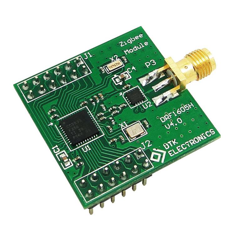
This module features serial to Zigbee wireless connection and pin pitch of 2.54 mm making it compatible with variety of boards. It can also directly interface with RS485 device and does not require external power supply. It can be powered via USB port power supply.
This module has built in RS485 direction control and can directly drive RS485, RS232 chip, and USB turn RS232 chip.
Zigbee module parameters:
- Input voltage
- Standard: DC 3.3V, range: 2.6V-3.6V
- Operating Temperature: -40°C~85°C
- Net weight 7.4g
- Serial port rate
- 38400bps (default), can be set to 9600bps, 19200bps, 38400bps, 57600bps, 115200bps
- Radio frequency
- 2.4G (2460MHz), the user can change the channel through the serial port command (2405MHz – 2480MHz, step: 5MHz)
- Wireless protocol
- Wireless Protocol: Zigbee 2007
- Transmission distance
- Visible, open, transmission distance of 1600 meters
- Working Current: 120 mA (emission), 80 mA(average), 45 mA(max receiving), 40mA (standby max)
- Interface: UART 3.3V TX-RX, RS485, RS232, USB turn RS232
- Receiving sensitivity: -110 dBm
- Main chip: CC2530F256, 256KFLASH, TI’s latest generation ZigBee SOC chip
- Configurable node: Configurable as Coordinator, Router
- The factory default is: Router, PAN ID=0x199B, channel=22 (2460MHz)
- Built-in RS485 direction control, can directly drive RS485 chip
- Can directly drive RS232 chip
- Can directly drive USB to RS232 chip
- Zigbee module pin definition and size
Details:
Model: DRF1605H, main function: serial port (UART) to Zigbee wireless data transparent transmission (fully compatible with DRF1605 PIN pin, transmission distance 1.6 km)
The factory default setting of the module is Router, users can switch to Coordiantor by themselves.
Main features of the Zigbee module
Automatic networking: All modules are automatically networked when they are powered on. If the modules in the network are powered off, the network has self-healing function.
Data transmission: Data can be transmitted between any node through the serial port:
1, data transparent transmission: the data received by the Coordinator from the serial port will be automatically sent to all nodes; the data received by a node from the serial port will be automatically sent to the Coordinator;
2, command mode, data transfer between any node: data transfer format: 0xFD (data transfer command) + 0x0A (data length) + 0x73 0x79 (target address) + 0x01 0x02 0x03 0x04 0x05 0x06 0x07 0x08 0x09 0x10 (data, A total of 0x0A Bytes).
Easy to use: users don’t have to consider the ZigBee protocol, use wireless modules like serial lines
This module can be used with USB backplane, no external power supply, USB port power supply and data transmission (USB to serial port). It is strongly recommended to purchase at least 1 USB backplane when purchasing DRF1605H Zigbee module, in order to debug and configure the module.
This module can be used with the RS485 backplane to transfer the DRF1605H’s UART port to the standard half-duplex RS485 interface, which can be directly connected to the RS485 device (the PIN pin is fully compatible with the DRF1605. The picture below shows the DRF1605 real shot photo).
The DRF1605H’s pin spacing is standard 2.54 or 2.54*n, so it can be plugged directly into the universal board for easy development (the PIN pin is fully compatible with the DRF1605. The picture below shows the DRF1605 real shot).
DRF1605H and MCU are very convenient to connect, fully support 51, ARM, X86, MIPS…. and other core MCU, as long as the MCU has a serial port:
Zigbee module networking:
The Zigbee network usually consists of three types of nodes: Coordinator: used to create a Zigbee network and assign addresses to nodes that originally joined the network. Each Zigbee network requires and only needs one Coordinator; Router: also known as Zigbee full-featured node, can Forward data, play the role of routing, can also send and receive data, as a data node, can also maintain the network, assign addresses to the nodes that join later; End Device: terminal node, usually defined as battery-powered low-power devices, usually Only data is sent periodically and no data is received.
The main function of this Zigbee module is wireless data transmission, that is, each node can send and receive data at any time. Therefore, the configuration of the node is only Coordinator and Router (the factory default is Router, the user can set the desired node type by configuration software or instructions) The connected network is shown in the figure below. Such a network is also commonly called MESH network (ie, mesh network). Each node can send and receive data, and can also serve as a router for other nodes. Moreover, all data transmission routes are It is automatically calculated without user intervention.
When using the Zigbee module for the first time, power on the Coordinator first, and then power on the Router. After the Router is powered on, it will automatically find the Zigbee network and join it. You can use TI’s Sensor Monitor software to observe the shape of the Zigbee network.
Steps for usage:
1. Connect the Coordinator module to the PC through the serial port, open the TI Sensor Monitor software, select the serial port number of the Coordinator connection, and click the RUN icon to run. At this point, you can see that the Coordinator icon turns red, indicating that the Coordinator is successfully connected to the PC. . (Note: TI Sensor Monitor software only supports the serial port baud rate of 38400);
2. Power on a Router module and press the TEST button. At this time, the Router module will send an analog data to the Coordinator. The Coordinator will send this data to the PC through the serial port and display the network structure in the TI Sensor Monitor software. ,As shown below. (The TEST button of DRF1605H is the 3rd pin (SW1) of J2, short-circuit with the ground)
3. Similarly, if other router modules are powered on, they will automatically find and join the network. Press the TEST button. The structure after networking is as follows:
4, the Coordinator can be directly bound to the six routers. After the other routers continue to join the network through the previous Router, each Router can accept the other six Routers to join the network and assign addresses:
Zigbee module data transmission
DRF1600 series Zigbee module data transmission function is very simple and easy to use, there are two ways of data transmission:
(1), data transparent transmission method:
As long as the first byte transmitted is not 0xFE, 0xFD or 0xFC, it will automatically enter the data transparent transmission mode;
The data received by the Coordinator from the serial port is automatically sent to all nodes;
The data received by a node from the serial port is automatically sent to the Coordinator;
(2), point-to-point data transmission method:
Data can be transmitted between any nodes in the Zigbee network through point-to-point transmission instructions;
Instruction format: 0xFD + data length + destination address + data
1, data transparent transmission: (data transparent transmission is the most important function of DRF1600 series module)
(1), as long as the first byte transmitted is not 0xFE, 0xFD or 0xFC, it automatically enters the data transparent transmission mode;
(Extension: As long as the header of the packet is different from the setting command, it will be transmitted as transparent data, but it is recommended that the user pass the data through
The first byte of the transmitted packet is set to non-FE, FD or FC, such as A7)
(2) The data received by the Coordinator from the serial port is automatically sent to all nodes; the data received by a node from the serial port,
Will be automatically sent to the Coordinator;
(3), between any node and the Coordinator, similar to the direct connection of the cable (in most cases, a Coordinator can be used,
1 Router directly replaces an RS232 cable;
(4), support packet lengthening (no need to set), the maximum does not exceed 256 bytes / data packet, the general application is recommended within 32 bytes of each packet.




Reviews
Clear filtersThere are no reviews yet.