Description:
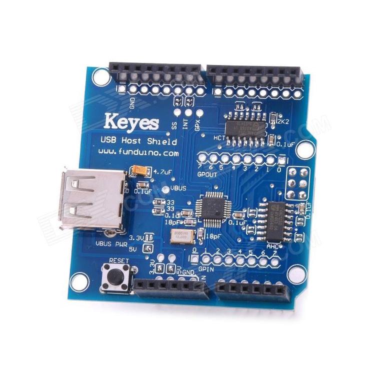
USB Host shields are available in two form factors – full size and Mini. Full size shield is designed to fit on top of “Standard” Arduinos, such as Uno, Duemilanove, Mega 1280/2560, and compatible clones. Full size shield has been designed for ease of use; it has plenty of empty space, features extra pads, solder jumpers and extensive silkscreen markings, simplifying board modification and troubleshooting. Full size shield is recommended for basic prototyping and simple projects. Mini shield main advantages are low size, weight and cost. Ideally, it should be used together with Arduino Pro Mini 3.3V board. It can be mated with other Arduino and non-Arduino MCU boards, but it takes more work. Small size, dense part placement and lack of silkscreen markings make this board more suitable for advanced projects, as well as semi-permanent and permanent installations, when basic functionality and wiring is already confirmed on larger prototype. Generally, modification and troubleshooting of Mini shield board is more difficult. Full-size shieldUSB Host Shield 2.0 exists in 2 configurations – “Standard” and “3.3V”. The layout of Standard board is depicted on the right. The board contains Maxim MAX3421E USB host controller, 12MHz crystal, level shifters, resistors, capacitors, Reset button and USB A-type connector. There are also a number of solder pads and jumpers, which are marked with red arrows. I start my explanation with an arrow close to Reset button and move counter-clockwise.

- Power Select 2 solder jumpers marked “5V” and “3.3V”. They are used for different power configurations. The configuration shown, when both jumpers are closed, is suitable for official Arduinos, such as UNO, Duemilanove, Mega and Mega 2560. See Power Options section for detailed explanation.
- Power pins are used to connect to power pins of Arduino board. RESET, 3.3V, 5V and GROUND signals from this connector are used.
- Analog pins are not used by the shield. They are provided to simplify mounting and provide pass-through for shields mounted atop of USB Host Shield in a stack.
- GPIN pins. Eight 3.3V general-purpose digital input pins of MAX3421E. They are used primarily to interface with buttons, rotary encoders and such. GPIN pins can also be programmed as a source of MAX3421E interrupt. An example of GPIN use can be seen in digital camera controller project.
- ICSP connector is used by the shield to send/receive data using SPI interface. SCK, MOSI, MISO and RESET signals from this connector are used.
- GPOUT pins are eight 3.3V general-purpose digital output pins of MAX3421E. They can be used for many purposes; I use it to drive HD44780-compatible character LCD, as can be seen in digital camera controller circuit, as well as this keyboard example. Max_LCD library which is part of standard USB Host library software package uses some of GPOUT pins.
- Digital I/O pins 0-7, like already mentioned analog pins are not used by the shield and provided only for convenience.
- Digital I/O pins 8-13. In this group, the shield in its default configuration uses pins 9 and 10 for INT and SS interface signals. However, standard-sized Arduino boards, such as Duemilanove and UNO have SPI signals routed to pins 11-13 in addition to ICSP connector, therefore shields using pins 11-13 combined with standard-sized Arduinos will interfere with SPI. INT and SS signals can be re-assigned to other pins (see below); SPI signals can not.
- MAX3421E interface padsare used to make shield modifications easier. Pads for SS and INT signals are routed to Arduino pins 10 and 9 via solder jumpers. In case pin is taken by other shield an re-routing is necessary, a trace is cut and corresponding pad is connected with another suitable Arduino I/O ping with a wire. To undo the operation, a wire is removed and jumper is closed. See interface modifications section for more information.GPX pin is not used and is available on a separate pad to facilitate further expansion. It can be used as a second interrupt pin of MAX3421E.
- VBUS power pad. This pad is used in advanced power configurations, described in Power Options section.





Reviews
Clear filtersThere are no reviews yet.