


Description:
Fingerprint scanners are awesome. Why use a key when you have one right at the tip of your finger? Unfortunately, they’re usually unreliable or difficult to implement. Well not anymore! We’ve found this great fingerprint module from ADH-Tech that communicates over TTL Serial so you can easily embed it into your next project.
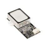
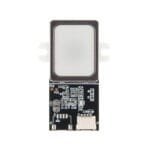
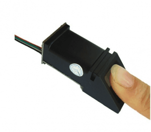
The module itself does all of the heavy lifting behind reading and identifying the fingerprints with an on-board optical sensor and 32-bit CPU. All you need to do is send it simple commands. To get started, just register each fingerprint that you want to store by sending the corresponding command and pressing your finger against the reader three times. The fingerprint scanner can store different fingerprints and the database of prints can even be downloaded from the unit and distributed to other modules. As well as the fingerprint “template,” the analyzed version of the print, you can also retrieve the image of a fingerprint and even pull raw images from the optical sensor!
This is the updated version of the GT-511 which has an increased memory capacity. The module can store up to 200 different fingerprints (that’s 10x more than the old version!) and is now capable of 360° recognition.
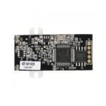
The module is small and easy to mount using two mounting tabs on the side of the sensor. The on-board JST-SH connector has four signals: Vcc, GND, Tx, Rx. A compatible JST-SH pigtail can be found in the related items below. Demo software for PC is available in the documents below, simply connect the module to your computer using an FTDI Breakout and start the software to read fingerprints!
Pin Configuration:

Pins 1 and 2 are 3.3V TTL pins used to communicate with the FPS module. The default baud rate is 9600bps after power on.
Pin 1 is the transmit pin of the UART on the FPS (UART Tx) and transmits a logic high of up to a maximum of 3.3V.
Pin 2 is the receive pin of the UART on the FPS (UART Rx) and can receive a logic high level of up to 3.3V. The voltage level sent to this pin from a microcontroller needs to be reduced when working with 5V microcontrollers.
Pin 3 is the common GND or 0V pin of the FPS module.
Pin 4 is the 5V input to the FPS module used to power it. This value can be between 4.5V and 6V.


Reviews
Clear filtersThere are no reviews yet.