STM32F103C8T6 “Blue-Pill” Microcontroller Development board | Core board ARM Cortex M3 processor
₨1,200.00 Original price was: ₨1,200.00.₨850.00Current price is: ₨850.00.
Introduction:
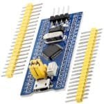
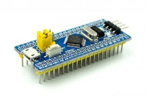
The Blue Pill is a development board based on STMicroelectronics’ STM32F103C8T6 microcontroller that has an ARM Cortex-M3 core that runs at 72MHz max. Software libraries are available that allow users to program the chip using the Arduino IDE.
More to know:
- Blue Pill Dev Board with ARM Cortex M3 processor, the Microcontroller for professionals
- 72 MHz 20 KB Ram 64 KB Flash 27 GPIOs
- USART / I2C / SPI / USB / CAN / DMA
Description:
Hardware resources:
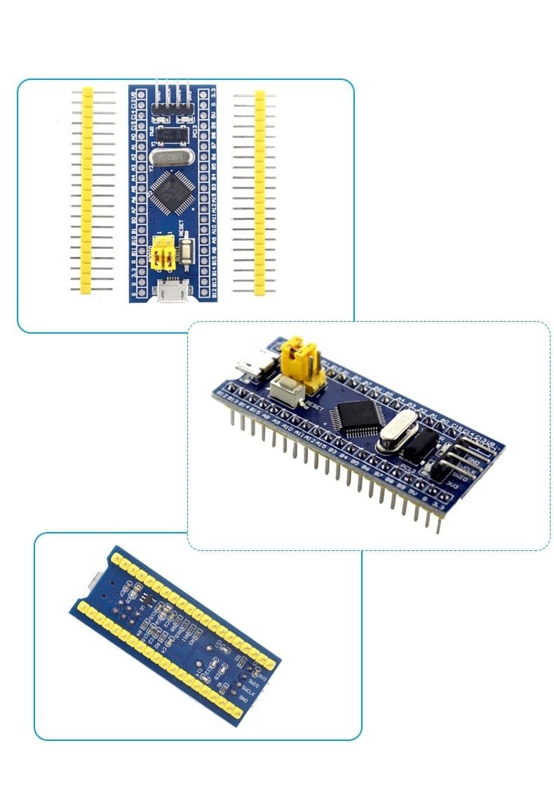
- One STM32F103C8 main chip
- SMD 8M crystal oscillator (up to 72M through the internal PLL of the chip) ST official standard parameters
- 3.3V voltage regulator chip, which can provide a maximum current of 800mA
- One mini USB interface, which can supply power to the system version and reserve USB communication function
- Reset button
- One standard SWD port, support JLink, STLink, JLINK OB
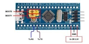
- BOOT select port
- IO expansion pin header 20pin x 2
- 1 power indicator light
- One function indicator is used to verify the essential functions of the IO port
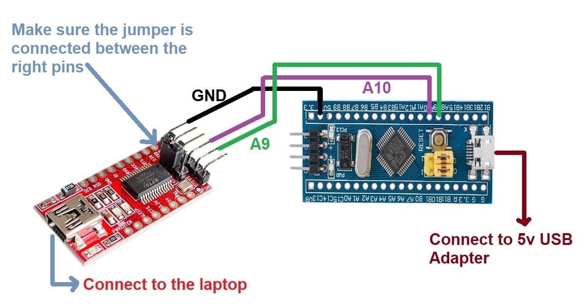
- The serial port is reserved for easy connection with the 5V development board, and the serial port can be used to program
- High-performance Epson 32768Hz crystal oscillator, the price is 10 times the price of the in-line crystal oscillator, easy to start the vibration
- 20K RAM, 64K ROM, TQFP48 package
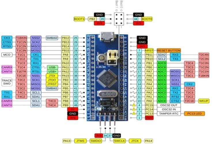
STM32F103C8T6 Blue Pill Pinout Configuration
Category |
Pin Name |
Details |
Power |
3.3V, 5V, GND |
|
Analog Pins |
PA0 – PA7 PB0 – PB1 |
Pins act as ADCs with 12-bit resolution |
Input/output pins |
PA0 – PA15 PB0 – PB15 PC13 – PC15 |
37 General-purpose I/O pins. |
Serial |
TX1, RX1 TX2, RX2 TX3, RX3 |
UART with RTS and CTS pins |
External interrupts |
PA0 – PA15 PB0 – PB15 PC13 – PC15 |
All digital pins have interrupt capability |
PWM |
PA0 – PA3 PA6 – PA10 PB0 – PB1 PB6 – PB9 |
15 PWM pins total |
SPI |
MISO0, MOSI0, SCK0, CS0 MISO1, MOSI1, SCK1, CS0 |
2 SPI |
Inbuilt LED |
PC13 |
LED to act as a general-purpose GPIO indicator |
I2C |
SCL1, SDA1 SCL2, SDA2 |
Inter-Integrated Circuit communication ports |
CAN |
CAN0TX, CAN0RX |
CAN bus ports |
STM32F103C8T6 Technical Specifications
Microcontroller |
STM32F103C8T6 |
Operating voltage |
3.3V |
Analog inputs |
10 |
Digital I/O pins |
37 |
DC source/sink from I/O pins |
6mA |
Flash memory (KB) |
64/128 |
SRAM |
20KB |
Frequency (clock speed) |
72MHz max. |
Communication |
I2C, SPI, UART, CAN, USB |
Package Included:
1 x Blue-Pill STM32F103C8T6 Development Module
You must be logged in to post a review.
Related products
Arduino DUE R3 Board SAM3X8E 32-bit Cortex-M3 Control Board Module
Overview:
Arduino Due Microcontroller Board based on the Atmel SAM3X8E ARM Cortex-M3 CPU. It is the first Arduino board based on a 32-bit ARM core microcontroller. It has 54 digital input/output pins (of which 12 can be used as PWM outputs), 12 analog inputs, 4 UARTs (hardware serial ports), a 84 MHz clock, an USB OTG capable connection, 2 DAC (digital to analog), 2 TWI, a power jack, an SPI header, a JTAG header, a reset button and an erase buttonArduino Ethernet Shield w/o PoE (Wiznet W5100)
(Get A latest Price)
Arduino MEGA 2560 R3 (ATMEGA2560-16AU MCU)
Overview
The Arduino Mega 2560 is a microcontroller board based on the ATmega2560 (datasheet). It has 54 digital input/output pins (of which 15 can be used as PWM outputs), 16 analog inputs, 4 UARTs (hardware serial ports), a 16 MHz crystal oscillator, a USB connection, a power jack, an ICSP header, and a reset button. It contains everything needed to support the microcontroller; simply connect it to a computer with a USB cable or power it with a AC-to-DC adapter or battery to get started. The Mega is compatible with most shields designed for the Arduino Duemilanove or Diecimila.Bluetooth Shield for Arduino (Master Slave)
GPS module SR-87 (ProGin)
Leonardo R3 Development Board ATMEGA32U4
Product specifications:
• Controller: ATmega32u4 • Work record: 16 MHz • Working voltage: 5V • Input voltage (recommended): 7-12V • Digital IO port: 20 • PWM channel: 7 • Analog input: 12 • 5V digital / analog port maximum allowable current: 40 mA • 3.3V digital / analog port maximum allowable current: 50 mA • Flash Memory: 32 KB (ATmega32u4) of which 4 KB used by bootloader • SRAM: 2.5 KB (ATmega32u4) • EEPROM: 1 KB (ATmega32u4)Simcom- SIM900
XBee 1mW Wire Antenna
Description:
- 3.3V @ 50mA
- 250kbps Max data rate
- 1mW output (+0dBm)
- 300ft (100m) range
- Wire antenna
- Fully FCC certified
- 6 10-bit ADC input pins
- 8 digital IO pins
- 128-bit encryption
- Local or over-air configuration
- AT or API command set
Reviews
There are no reviews yet.